RBENREJEB@RBR-OS:/USR/SHARE/DOC/LINUX-THERMALRIGHT-LCD-CONTROL/ADD-NEW-DEVICE$ CAT README
Add a new device
Thermalright LCD Control For Linux · Documentation
There are two ways to add support for a new device:
- Generic device (recommended, no code): describe the device (transport, image encoding, frame header) from the
GUI with the + button, or in a small
device_<id>.yamlfile. The data-driven generic driver does the rest. - Native device (Python code): write a dedicated device class, for protocols the generic driver cannot express.
If your device is close to a supported one, start with the generic driver and try the bundled values first. If you do not know the header or encoding of your device, the how-to at the end of this chapter explains how they were found for the supported devices, by capturing the USB traffic of the Thermalright Windows software.
Adding a generic device (no code)
You need to know the header, the image encoding and the transport your device uses. In most cases that is all the generic driver needs.
From the GUI
The add-device form is the easiest way. No file editing and no restart are needed: once you add it, the device is registered and starts displaying immediately.
- Click the + button in the title bar to open the add-device dialog.
- Pick your device from the Connected USB devices list. The dialog lists the USB devices currently plugged in
(via
lsusb), so you can select yours by name and VID:PID instead of typing the ids.- If the VID:PID is in the probe registry, the device is probed and the whole form is pre-filled: you can just add it.
- Otherwise, fill in the fields yourself (see The device file: resolution, transport, encoding, header and the optional transport-specific fields under Advanced).
- Leave Driver mode on Generic to use the data-driven driver. Switch to Native only if your device needs one of the hard-coded device classes.
- Check the suggested Id. The dialog proposes
<pid>_<vid>_<bus>_<device>so two identical displays stay distinct; you can keep it in most cases. - Click Add device. The dialog writes the
device_<id>.yamlfile, the device appears as a new tab, and it starts rendering right away with a default theme for its resolution.
If the device shows nothing, or a blurry or scrambled image, the header or encoding is not right yet: click Edit this device, adjust the header or encoding, and click Save changes (see The device file and The screen displays a blurry image).
The device file
Each registered device is one device_<id>.yaml file in the config directory
(~/.config/thermalright-lcd-control/config for an installed application, resources/config when running from the
sources). You can also create it by hand. Example for the 0416:5302 device:
id: 5302_0416_3_4
vid: 0x0416
pid: 0x5302
width: 320
height: 240
generic: true
transport: hid
chunk_size: 4096
encoding: rgb565_le_columns
report_id: "00"
header:
  prefix: "DADBDCDD"
  format: "<6HIH"
  values: [2, 1, width, height, 2, 0, payload_size, 0]
| Field | Description |
|---|---|
id |
Unique device id, also used to name the active theme file (config_<id>.yaml). |
vid / pid |
USB ids, as shown by lsusb. |
width / height |
Screen resolution in pixels. |
generic |
true for the data-driven driver, false to use a native device class. |
transport |
How frames are sent to the device (see below). |
chunk_size |
Size in bytes of each write. In Wireshark it corresponds to usb.data_len. |
encoding |
How the image is encoded (see below). |
header |
The frame header, static or computed per frame (see below). |
Transports:
hid: HID interface (hidapi).usb_bulk: plain USB bulk endpoint.usb_bulk_ly: USB bulk with the “LY” handshake and a chunked JPEG protocol.scsi: USB Mass Storage / SCSI commands.
Encodings:
rgb565_le_columns: RGB565 little-endian, column-major with vertical flip.rgb565_be: RGB565 big-endian, row-major.jpeg: JPEG-compressed frame (seejpeg_quality).
Header:
- Static:
header: {static: "dadbdcdd0200..."}with the full hex string extracted from a capture. - Computed:
prefix(fixed hex bytes) +format(a Python struct format) +values. Each value is a literal integer, a hex string, or one of the placeholderswidth,height,payload_sizeandcmd, resolved for every frame. - Omit
headerentirely if your device takes the raw payload with no header.
Optional fields, depending on the transport:
| Field | Description | Default |
|---|---|---|
report_id |
Hex byte(s) prepended to every HID packet. | "00" |
cmd |
Value substituted for the cmd header placeholder. |
|
command |
SCSI opcode for the scsi transport. |
0xF5 |
jpeg_quality |
JPEG quality for the jpeg encoding. |
85 |
ep_in |
IN endpoint address used to read handshake replies. | 0x81 |
start_wait |
Seconds to wait before sending the first frame. |
Once the file is in the config directory, the device appears in the device list and gets its own active theme file,
config_<id>.yaml.
Probe registry (known devices)
Known devices are listed in the probe registry,
src/thermalright_lcd_control/device_controller/display/probe_registry/,
one YAML file per VID:PID named <VID>x<PID>.yaml:
# Winbond USBDISPLAY — HID type 2 (DA DB DC DD handshake).
vid: 0x0416
pid: 0x5302
name: Winbond USBDISPLAY (HID type 2)
probe: hid_t2
probe names the handshake family the device speaks: bulk, hid_t2, hid_t3, ly or scsi. When a registered
VID:PID is connected, the application sends that family’s handshake; the device’s answer gives its resolution and
encoding, and the family defaults fill in the header, report id and chunk size. That is how known devices are
detected automatically and how the add-device form gets pre-filled.
If your device speaks one of these families under a VID:PID that is not listed, add a registry file for it and
please contribute it, so the next user gets it detected automatically. A new handshake family needs code in
device_probe.py.
Adding a native device (Python code)
If your device protocol cannot be expressed with the generic driver (special handshake, exotic encoding…), implement
a device class. An example with commentary is available in new_device_example.py.
- Name the class following the convention in
new_device_example.py. Do not name it after your product: the same VID/PID can be used in several products. - Add the class to
hid_devices.pyif the device uses the HID interface, or tousb_devices.pyif it uses USB. You can also create a new file instead; put the VID/PID in its name, for exampledevice_0418_5304.py. - Add your device to the
SUPPORTED_DEVICESvariable insupported_devices.py. - Register the device with
generic: falsein itsdevice_<id>.yamlfile (see The device file): the native class is resolved from the VID/PID and resolution. - If there is no preset theme for your resolution, create one (see Add a default theme).
- Stop the Windows VM if it is running, so it releases the device, then start the application from the sources:
uv run thermalright-lcd-control-app --config resources/gui_config.yaml
If all the steps went well, your device is working.
The screen displays a blurry image
A blurry or scrambled image means the image is not encoded the way the device expects.
For a generic device, first try the other encoding values in the device file: that is often enough. If none of
them works, you need to find out how the image is encoded for your device and implement it in a native device class.
Images can be scanned in many ways: horizontally or vertically, from left to right or right to left. To figure out which one your device uses:
- Prepare two simple colour-bar images with the screen resolution: one with horizontal bars and one with vertical bars.
- Redo all the capture steps for these images, plus the plain green image, until you have a clean output file for each.
- Using the green image, find the value of the row separator (for example the
0000sequence) and count the number of hex characters between two separators. - In the three files, remove the header and the trailing padding of the last line (everything after the last
f597in the green image), and remove the\nor\rat the end of each line.
An AI assistant was used to find the encoding of the supported devices: give it the three images and their outputs, explain the separator logic, and ask it for the encoding algorithm. To check its answer, ask it to generate an output file with its code and compare it to yours. If they are not exactly the same, it must try another algorithm, and so on until it finds the right one. Most of the effort is in preparing clean files it can work from.
Add foregrounds for the new device
If no bundled foreground matches your resolution, create the folder
resources/themes/foregrounds/<width><height> and add foregrounds suited to your screen.
You can take them from the Thermalright Windows software: the bundled ones come from TRCCAPEN\Data\USBLCD\Web.
Foregrounds are in the zt* folders; pick the one that matches your screen resolution. Each contains subfolders with
the foreground image, a config file and a preview of the theme. Copy the PNG files to
resources/themes/foregrounds/<width><height>.
Add a default theme
The bundled themes of a resolution are the theme_*.yaml files in resources/themes/presets/<width><height>/.
When a device is used for the first time, the first of them in alphabetical order (usually theme_1.yaml) becomes
its active theme. If the folder is missing or empty, the device starts with a plain background and no foreground or
widgets.
- Run the application from the sources:
uv run thermalright-lcd-control-app --config resources/gui_config.yaml - Configure a theme and save it with Save theme. It is saved as
resources/themes/presets/<width><height>/user_<name>.yaml. - Rename it
theme_<n>.yaml, so it becomes a bundled preset. Name ittheme_1.yamlto make it the default. - Check the media paths in the file: like the other presets, they must point under
./resources/themes/and use the{resolution}placeholder for the resolution folder, for example./resources/themes/backgrounds/{resolution}/theme_1.png.
If you start from a copy of another resolution’s preset instead, set foreground.enabled to false until
foregrounds exist for your resolution.
The theme then ships with the application as a preset for that resolution, and the application is ready to be packaged.
How to find out how a device works
This section explains how the protocol of the supported devices was found, by capturing the USB traffic of the Thermalright Windows software. Once you know the header, encoding and transport of your device, add it with the generic driver or as a native device.
Application architecture
The application has two parts:
- the GUI, which configures and customizes what is displayed on the screen;
- the device controller, which talks to the device. Since v2.0 it runs inside the GUI process, with device access granted by udev rules.
Configuration files:
| File | Content |
|---|---|
gui_config.yaml |
GUI configuration, under resources. |
device_<id>.yaml |
One file per registered device: VID/PID, resolution, transport, encoding, header… |
config_<id>.yaml |
What the device displays: background, foreground, metrics… |
themes/presets/<width><height>/theme_*.yaml |
Bundled preset themes per resolution; the first one seeds config_<id>.yaml. Under resources. |
The entry point is main_app.py, which starts the GUI and the device controller. To run from the sources:
uv run thermalright-lcd-control-app --config resources/gui_config.yaml
Tools
- A Windows virtual machine in VirtualBox, with the official Thermalright software installed.
- Wireshark.
- The
tsharkcommand-line tool.
Configuring the official software
In the Windows VM, configure the display with a plain colour background, with no foreground or text: really just the background.
The official software adds many sequences of 0x00 to the packets, for the report id and as a separator for each row
of pixels. Using the green background makes them easy to find: its hex value contains no 0x00 at all, so every
0x00 is extra technical information. Each packet also starts with a header, which is hard to spot without the green
background.
Save your configuration and make sure the software uses it again after a restart.
Capturing packets
Load the usbmon module so Wireshark can read USB traffic:
sudo modprobe usbmon
Use lsusb to find the bus id and device id of the display:

Here the bus id is 3 and the device id is 4.
Run Wireshark with sudo and select usbmon<bus id>, here usbmon3. To show only the packets sent to the device,
use this filter:
usb.device_address == <device id> && usb.transfer_type == 0x01 && usb.endpoint_address == 0x02 && usb.src == "host"
usb.device_address: the device id, here 4.usb.transfer_type:0x01for data transfer.usb.endpoint_address:0x02for data transfer.usb.src:hostfor data sent to the device.
If the software is running and the filter shows no packets, remove usb.transfer_type and usb.endpoint_address one
at a time to find the one that does not match, then find its correct value:
- Select the packet with the biggest length.
- Unfold the USB URB section.
- For
usb.transfer_type, right-click URB transfer type and select Apply as Filter ▸ …and Selected. - For
usb.endpoint_address, right-click Endpoint and select Apply as Filter ▸ …and Selected.
Then capture the frames:
-
In the Windows VM, keep the software running and disable the display’s USB device in the VirtualBox USB settings:
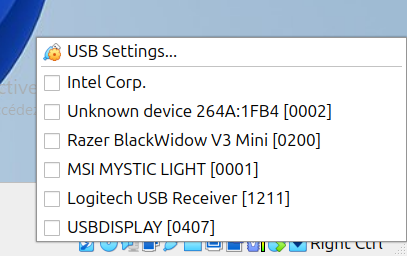
- Restart the capture in Wireshark. If asked to save, select Continue without saving. With the filter applied and the USB device disabled, no packets should appear.
- Enable the display’s USB device again in VirtualBox and wait for packets to appear.
- Click Stop about a second after the first packets appear.
- Select File ▸ Export Specified Packets, choose a folder and file name, and click Save.
Extracting the data
Only Wireshark can read the capture file. Extract the data into a plain text file in hexadecimal:
tshark -r /path-to-capture/yourcapturefile.pcapng -T fields -e usb.capdata > output.txt
Use the field that matches what Wireshark shows for the data:
usb.capdataif the section is called Leftover Capture Data;usbhid.dataif the section is called HID Data.
Check that output.txt contains the data you want.
Cleaning the output
Even if you stop the capture quickly, you will end up with several copies of the packets that make up the image. The
output.txt example in the repository
shows what you should get. To clean it:
- The first line can usually be removed: the supported devices work without it.
- The second line is the start of the group of packets that make up the image.
- Find the next occurrence of that line and remove everything from there to the end of the file.
You end up with a file like
output_clean.txt. In that
example:
- The image is a sequence of
f597, the hex value of the green colour. - The header is everything before the first
f597:dadbdcdd02000100f000400102000000005802000000. - The last line ends with a sequence of
00after the lastf597: the last part of the image is shorter than 512 bytes, so it is padded. - A
0000separator appears every 956 characters, between sequences off597. It separates the rows: the image is scanned from bottom to top and from left to right, and the separator is added each time the scan reaches the top.
With the header, encoding and transport known, add the device.